A previous blog What Size of Porosity Can Vacuum Impregnation Seal? discussed that porosity occurs naturally and that the purpose vacuum impregnation is to seal leak paths created by interconnected pores. This follow up blog discusses how to define what leak paths should be sealed.
It is important to understand that all materials permit leakage over time. In order for vacuum impregnation to effectively seal the leak and maximize the amount of acceptable parts, the manufacturer needs to define the part’s performance requirements, and develop measurable and repeatable standards around those needs. Defining these standards is done through leak rate testing. Vacuum impregnation is then used to seal specific leak paths to achieve the pre-defined leak rate.
Purpose of Leak Rate Testing
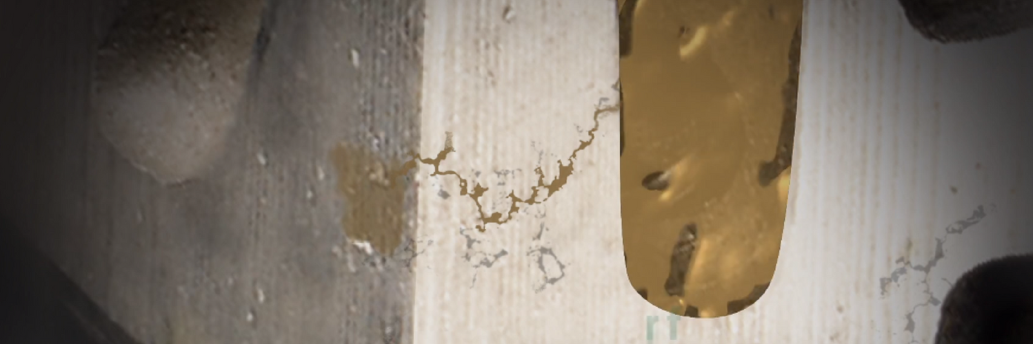
The purpose of leak rate testing is to confirm that the manufacturing process is performing to specification and making acceptable parts. Finding defective parts early in the manufacturing process will reduce field failures, minimize unforeseen costs, and improve customer satisfaction (Image 1).

Image 1: Identifying defective parts with leak paths will reduce field failures, minimize unforeseen costs, and improve customer satisfaction.
Setting a Leak Rate Standard
Inspecting die castings requires quantitative, measurable values that define what is and isn’t acceptable given a part’s intended use. The fact is even materials cast with careful processes will allow some leakage, given enough time. Casting manufacturers develop and adhere to leak rate standards. Such standards define the maximum tolerable leakage for a part, typically specified by cc/min at a specified pressure and time duration.
Air vs. Liquid Leak Testing
Most automotive components operate with liquid. However, air is primarily used in leak rate testing for the following reasons:
- Air is compressible and has a lower viscosity than liquid. Air can travel through a leak approximately 100-400 times faster than a liquid.
- Air has no surface tension. This allows it to escape a leak more easily than a liquid.
- Overall, testing methods using air are faster to conduct than those using a liquid.
Understanding Testing Protocols
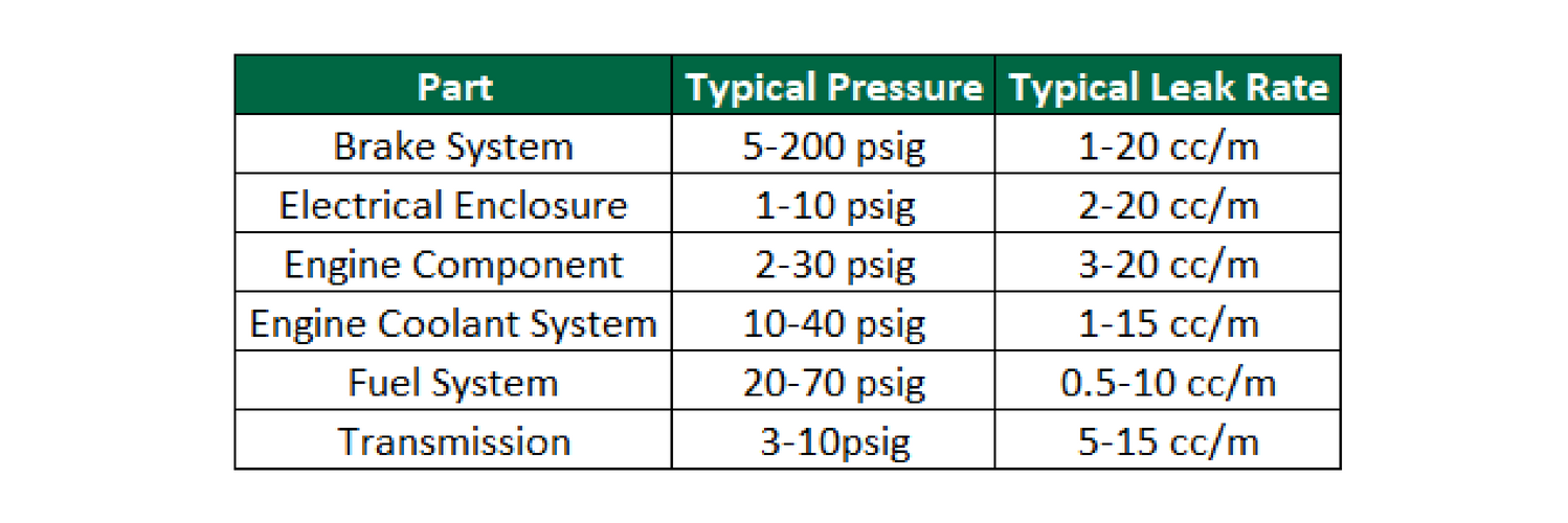
To save time and resources, most manufacturers use the industry-recognized leak rates that are available for many products. Figure 1 shows typical ranges for existing parts.

Figure 1
At times, industry recognized standards are not relevant for a part’s application. To establish new standards, those parts should be analyzed through the following steps:
- Test a large sample of production parts with an air leak tester at the same part working pressure.
- Pressurize parts with water at the same working pressure. This testing identifies the approximate hole size (measured by air leak rate) that does not allow fluid to flow through. The part’s resistance to fluid flow is defined by the hole diameter, part length, hole surface finish, fluid viscosity, and surface tension.
- Set the reject leak rate at a point close to but below the highest air leak rate that does not allow fluid to leak.
- The final leak rate tolerance should be stated as “specified air leak rate at a specified test pressure and time duration”.
It is important to note that even after a casting is sealed and passes the leak test criteria, the casting can still exhibit leaks under more aggressive test conditions. Recall that all materials will leak in varying degrees. If the test standards were established so that the casting would hold oil a 1 bar, it may still exhibit a leak if tested with air or helium at 1 bar. Gasses are thinner than liquids (e.x. sealant, oil, etc.) and will leak through a path that would not pass fluids.
What is the Role of Vacuum Impregnation in this Process?
Once a leak rate is defined, parts within that range can be sealed through vacuum impregnation. Parts outside of the leak rate parameters are typically scrapped.
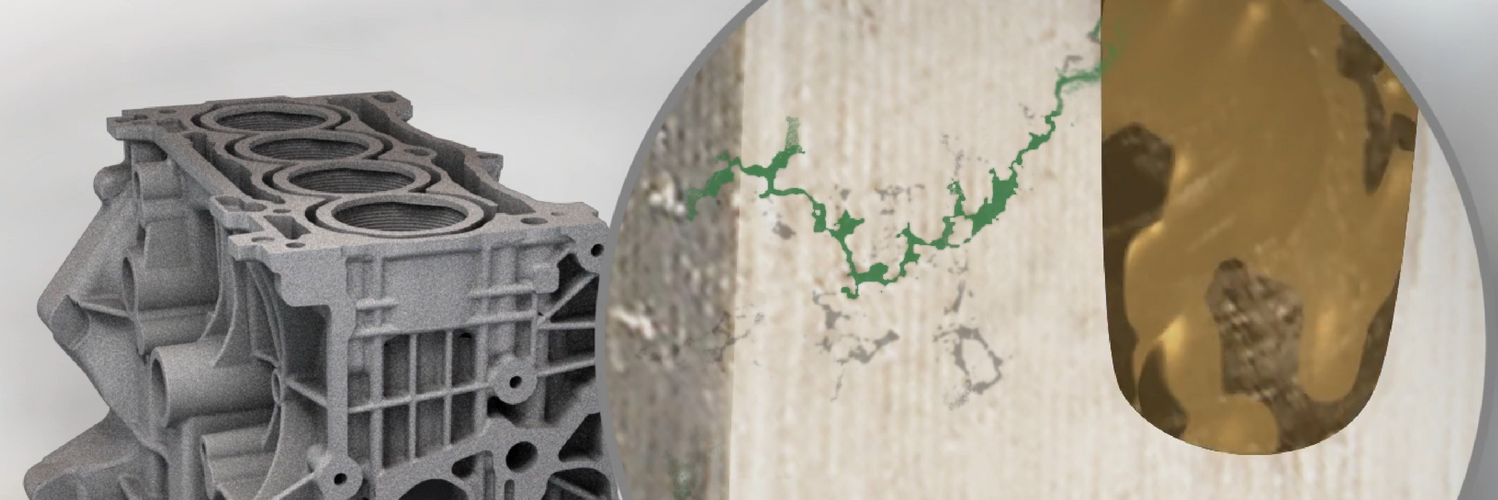
Vacuum Impregnation is a process that seals metal casting porosity. Specifically, it seals the internal, interconnecting path of porosity, which breaches the casting wall (Image 2). The process is not a surface treatment, so it does not seal open pores found on the casting surface. Nor is it intended to seal casting structural defects such as cracks or open knit lines.

Image 2: Vacuum impregnation seals this leak path (highlighted in green) so that fluids do not seep from the part.
In Summary
The wide range of casting parameters creates a limitless array of shapes and sizes of porosity possibilities. Despite this, vacuum impregnation can seal porosity of any size. While vacuum impregnation can seal porosity of any size, it is important to realize that the leak path is the key characteristic to evaluate and not pore size. A leak path is created through a series of interconnect pores, and not a single pore. Instead of asking “What size of porosity can vacuum impregnation seal?” one should ask “Can vacuum impregnation seal the leak path?”

